Creating Schema Using Data Parser
If you have a file but not an external definition of that file (that is, XSD/DTD, COBOL Copybook, Btrieve dictionary file), you can use the Data Parser to examine the file using various properties (that is, encodings) to discern record lengths or record separators, field lengths or separators, end of file markers, set discrimination rules for multiple record type files.
Note: You can use the Data Parser only for source schema type and not for the target.
Data Parser enables you to do the following for flat binary, fixed-length ASCII, or record manager files:
• Define source record length
• Define source field sizes and data types
• Define source data properties
• Assign source field names
• Define schemas with multiple record types
If you do not have a pre-defined layout or if you prefer to view data as you separate it into records and fields, use Data Parser.
The limitations of Data Parser are:
• You cannot use the Data Parser to parse Fujitsu COBOL files.
• The Unicode (Fixed) connector is not supported in the Data Parser under these conditions:
– When UTF-8, UTF-16, or UCS-2 encoding is used.
– When the CharFieldWidths property is set to byte-width (False). This limitation occurs when a connector uses character-width (True) to determine field width.
To create a schema using data parser:
1. Make sure the DataConnect Perspective is selected.
2. Select a DataConnect project and do any of the following:
• Go to File > New > Schema.
• Click the arrow in

and then click
Schema.
• Right-click on the project and then click New > Schema.
The New Schema File page is displayed.
| If v9 compatibility mode is enabled, then when you select any of the preceding option, the Select a Schema Type window is displayed. Select Structured Schema and click Next. |
3. Select the project where you want to create the schema and in the Schema File Name field, type a name for the schema, and click Next.
The Select Schema Type and Connector page is displayed.
4. Specify the following:
• Choose Schema Type - Select Source to create a schema for the source data.
• Choose Connector - From the drop-down list, select a connector. Connections determine the data types that will be used in building the schema.
5. Click Next.
The Select Schema Creation Method page is displayed.
6. Select Use Data Parser and click Next.
Note: If the Use Data Parser option is disabled, then you have selected a source type that the Data Parser cannot parse, such as ASCII (Delimited). For source types that cannot be parsed, you can use the Data Browser.
The Define Your Connection page is displayed.
7. Specify the connector and the related properties. For information about the connector properties, see
Map Connectors.
You may want to change the StartOffset property, which sets the number of bytes that must be ignored at the start of a file before the first record. To determine the starting offset of a file, see
Map Connectors.
8. Click Next.
The Data Parser page is displayed.
9. Specify the information in the various fields.
10. Click Finish.
A new schema file is created and it opens as a separate tab. The file extension for schema is .schema. The tree view displays the records, fields, and recognition rules that you specified using the data parser.
Using Data Parser
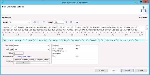
The Data Parser view displays the contents of the current file. You can view and define fixed positions of fields in the current file.
The Data Parser window display the correlation between the slider and the fields. Any changes in the fields are reflected immediately on the slider.
The following image displays the Data Parser window.
You can do the following in the Data Parser:
Viewing Records
To view records in the parsing panel, from the Records drop-down list, select the required record. The selected record and the fields are displayed in the parsing area.
Adding or Deleting Records
To add a record, next to the
Record drop-down list, click

. A record is added in the
Record drop-down list. To edit the name, highlight the name in the box, type the new name, and press
Enter.
The new record type or field is displayed in the list and becomes the focus in the parsing area.
To delete a record, from the
Record drop-down list, select the required record and click

. A message asking for confirmation is displayed. Click
Yes. The selected record is deleted.
Clearing Fields
To clear the fields defined for a record in this schema:
1. From the Record drop-down list, select the record for which you want to clear the fields.
2. Click

.
All the fields are cleared.
Browsing Data
To view the newly parsed structured data, click

.
Changing Font
To change the font, click

. The
Preferences window displays the
Data Parser Fonts options. For more information, see Setting Schema Preferences section in
Managing Schemas.
Defining Source Record Length
The record length is the total number of bytes of data in one record. The Starting Offset is any unwanted data at the beginning of a file that you want skipped. You must set the Starting Offset and/or Record Length correctly before you define the fields for each record type. If your file has only one record type, like most files, you only need to define the record length once.
By default, the Data Parser displays 100 bytes per line by default in the data display box. Fixed ASCII with record separators, C-tree, C-tree Plus, and Micro Focus COBOL indexed files are exceptions; Schema Designer sets the record length automatically based on the record separators in those files.
After you specify the starting offset and record length, you can define the field sizes, data types, and data and field properties for each field in one record type. Schema Designer uses this information to read each record in your source file. If the data extends beyond the right margin of the data display window, use the horizontal scroll bar to view one entire record per line.
The Starting Offset property is only used in Schema Designer and Data Parser as a visual reference. The starting offset has to be set when you select the connector.
Note: Only certain connector types have StartOffset as a source property. For instance, ASCII and Binary connectors have it, but a database connector such as Oracle does not.
If you know the record length, your source file has no record separators and only one record type, then in the Length field, type the required value to specify the length of the record. The default value is 100.
If you do not know the record length and have only one record type, click

. The
Fine Controls for Record Length dialog box is displayed, where you can set the end of the record.
Setting Start of Record
To set the start of the record:
• Specify the StartOffset value in the connector properties grid before clicking Connect on the Define Your Connection page.
• If you have not set the StartOffset value when connecting to the data, then click Back to return to the Define Your Connection page. Specify the StartOffset value in the connector properties grid, click Refresh, and then click Next to go to the Data Parser page.
If you want to eliminate a header or record(s) from the data transfer, change the value to specify how many bytes from the start of the file Map Designer should begin reading the data.
You can also do the following:
• Click the right arrow in the horizontal scroll bar until the first byte of the first required record is highlighted in pink. The right arrow in the horizontal scroll bar moves the byte position marker one byte per click to the right along the data displayed in the window. If you hold down the mouse button on the right arrow, the byte position marker will move quickly to the right until you release it.
• When you click inside the right arrow in the horizontal scroll bar, the byte position marker will move 78 bytes to the right in the data (or one screen width) per click. If you hold down the mouse button, the byte position marker will move quickly to the right in 78 byte increments until you release the mouse button.
Note: A tooltip is displayed for each marker that is added on the slider.
• Make a note of the number now displayed in the Set Start of Record box. This is the starting offset of the record. After setting the end of record, set the starting offset on the Define Your Connection window.
Setting End of Record
The end of record specifies the last byte number for a record in your data file. When combined with the Start of Record, it sets the total record length.
To set the end of record:
1. If you know the record length, in the Set End of Record field, type in the value minus one (this is because the first byte of the record is considered to be in position 0) plus the starting offset (if specified). For example, if your record length is 109 and the starting offset is 10, type 118.
2. If you do not know the record length, click the right arrow in the horizontal scroll bar until the last byte of the first required record is highlighted in pink. Clicking the left arrow moves the byte position marker one byte per click to the left along the data.
3. If you have a multiple record type file with different record lengths, set the record length to the correct length for the record name you are working on.
4. Verify the record length is set correctly by seeing that the last byte of the first desired record is highlighted in pink.
5. Click OK to close the dialog box.
When the data in the parser display starts in the correct place and shows only one record per line, the record length and starting offset are set correctly.
Specifying Fields, Properties, and Data Type
To define the fields, its properties, and the data type:
1. Define the field size for Field 1 by positioning the mouse in the string of data in the first record where you want the first field break. The pointer changes to an "I", which you can position between two characters (if you are on the pale blue line of data.
2. Click the required position to define the length of Field 1. A vertical arrow appears in the space just above the first line of data in that position. If you click the wrong position and want to correct it, place the pointer in the incorrect position (not on the arrow) and click again. The arrow must disappear. Then, click the correct position.
Tip: Define the field sizes sequentially from left to right along the line of data (appears in pale blue color). If you incorrectly define the size of a field, you can redefine all the fields to the right of the corrected field.
3. Define the data type for Field 1 if it is not character (text) data. Available data types are specific to the Source type. For details, see the specific Source Type in Connectors.
4. Based on the position of the arrow, the following fields are populated:
• Field Name: Displays the name of the currently defined field. By default, the fields are added as Field1, Field2, Field3, and so on. To rename it, click the name, type the required name, and press Enter.
Select a field to view its properties on the right. The following properties are displayed:
– Field Required – Select Yes or No to indicate whether this field is required or not. The default value is No.
– Default Expression – Click within the field and then click <icon> to open the EZscript Expressions window, where you can specify an expression for the field.
– Description – Type a description for the field.
– Size – Displays the size based on the position of the arrow in the slider.
• Data Type: Displays the data type in the field. To change it, select the required data type from the drop-down list.
• Offset: Displays the starting byte number for the field. If you type a value, the arrow moves in the slider to indicate the same.
• Contents: Shows the actual data in the field in the first record. (For all packed data types, this box displays unpacked data only after the correct data type is selected.)
5. Repeat steps 1 through 4 for each field in the record.
Specifying Discriminator and Recognition Rules
If you define more than one record type for a single file, you must set a discriminator field and define the recognition rules. The layout and rules together distinguish record types in the source file.
To set the discriminator field, from the Field Name drop-down list, select the field that you want to set as the discriminator for this file, and select the Discriminator option.
To set the recognition rule, click
Recognition Rules. The
Add Recognition Rules dialog box is displayed. You can add, delete, reorder the rules. For more information see
Managing Rules for a Record.
Note: If you have not selected the Discriminator option, then you can specify it in the Add Recognition Rules dialog box.
Data Parser Display Mode Options
The following table provides the display mode options for Data Parser.
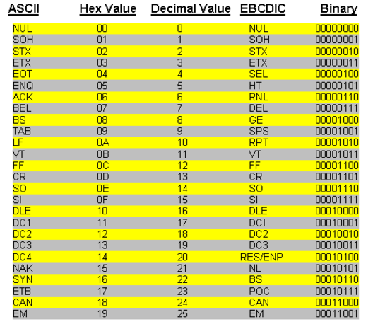
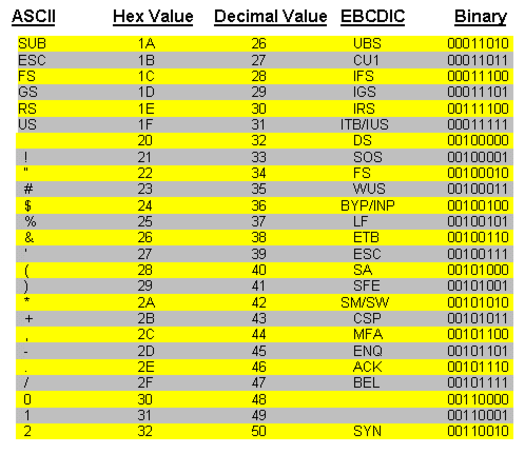
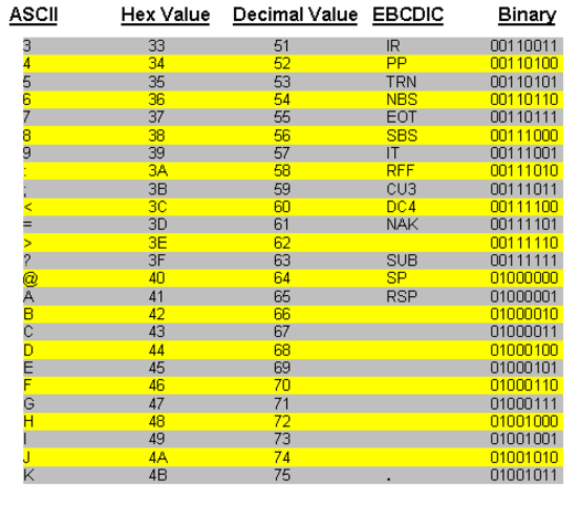
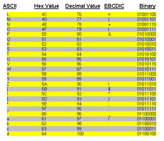
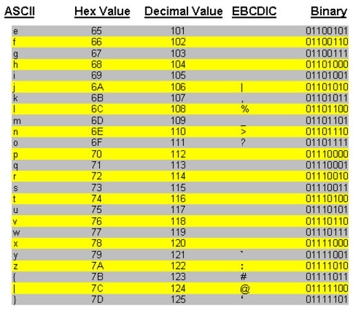
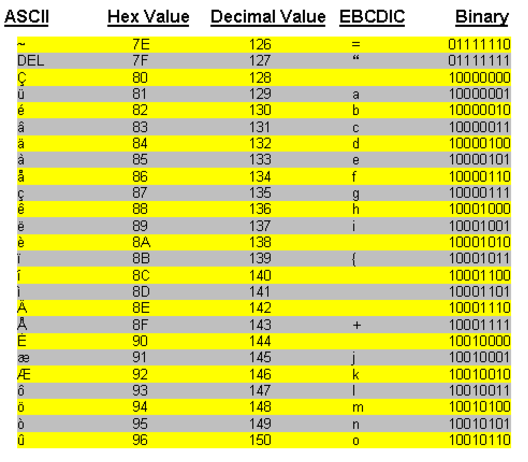
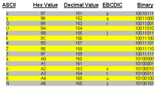
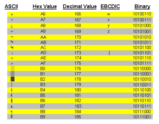
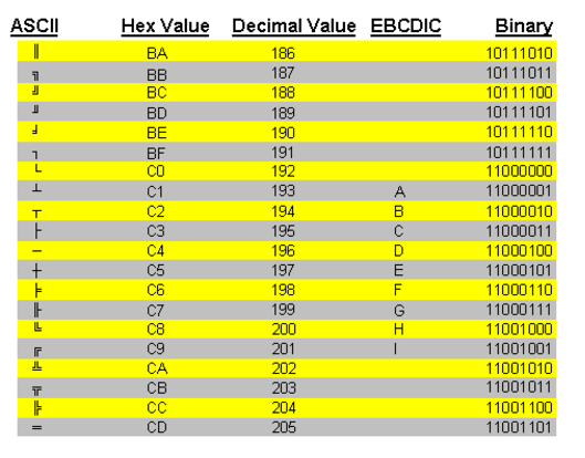
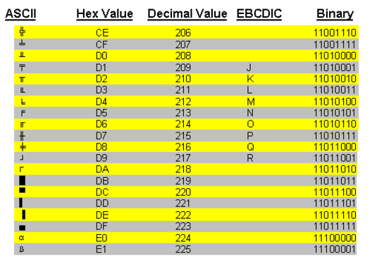
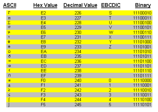
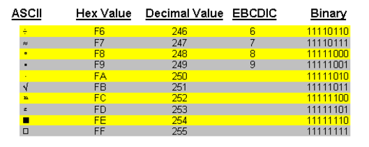
Hex Values Reference Chart
This chart presents the list of 256 standard and extended ASCII characters, as well as the corresponding hex, decimal, EBCDIC, and binary values for each character. They are included here as a reference for identifying record and field separators in delimited ASCII files.
Escaping hex values in regular expressions is supported.
 and then click Schema.
 and then click Schema.
 and then click Schema.
 . A record is added in the Record drop-down list. To edit the name, highlight the name in the box, type the new name, and press Enter.
 . A message asking for confirmation is displayed. Click Yes. The selected record is deleted.
 .
. .
. . The Preferences window displays the Data Parser Fonts options. For more information, see Setting Schema Preferences section in Managing Schemas.
 . The Fine Controls for Record Length dialog box is displayed, where you can set the end of the record.